Testing Ignition Coils:
Coil Specs (1):
Number: CTI - 118
Voltage: 12V
Primary: 1 - 1.3 ohms
Secondary: 8.5 - 9.5K ohms
Coil Specs (2):
Number: C6R - 500
Voltage: 12V
Primary: 1.2 - 1.5 ohms
Secondary: 6.5 - 8.5K ohms
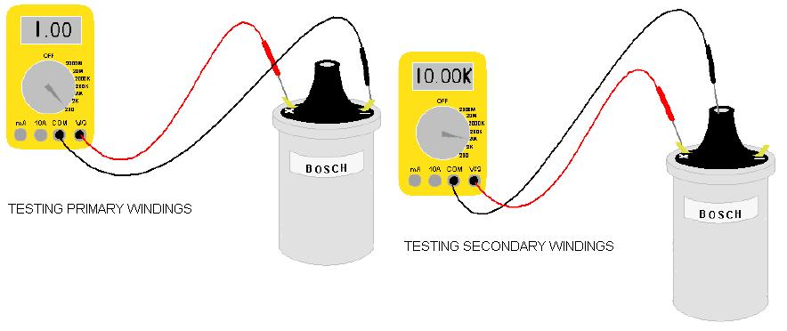
Coil 1 Test Results:
Primary: 1.7 ohms
Secondary: 9.4K ohms
Earth leakage test: Infinity
Coil 2 Test Results:
Primary: 1.9 ohms
Secondary: 8.2K ohms
Earth leakage test: Infinity
Wasted Spark Coil Pack:
Coil 1 test:
Secondary: 7.07K ohms
Coil 2 test:
Secondary: 7.07K ohms
Testing Ballast Resistor:
Ballast resistor measured at 2.1 ohms
Measuring Current Draw and Voltage Drop:
Current Draw: 3.76 A
Coil calculated voltage drop: 1.7 x 3.76 = 6.392v
Coil measured voltage drop: 4.22v
Ballast resistor calculated voltage drop: 3.76 x 2.1 = 7.896v
Ballast resistor measured voltage drop: 6.96v
My calculated values did not equal my measured results because my calculated voltage drop was higher than my measured voltage drop.
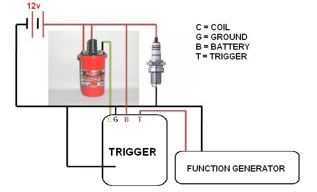
Wiring up ignition systems:
Ignition module using a function generator to trigger the module.
Wasted Spark System:
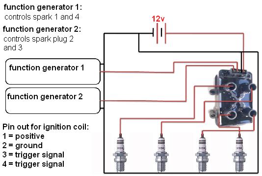
Ignition module using a distributor:
Tuesday, September 7, 2010
Thursday, August 26, 2010
SENSORS
This type of TPS is a resistor variable.
As the throttle position changes, the output voltage from the sensor changes. At idle position it is recognized by the lowest voltage reading through the sensor but in contrast, the maximum power signal is recognized by the highest reading at full position of the sensor travel.
Manifold Absolute Pressure (MAP)
Map sensor reads vacuum.
As vacuum is applied the voltage reading changes. The more vacuum applied the higher the output voltage reading is for the sensor.
Air Flow / Mass Sensors (MAF)
The voltage reading I got when I first powered up the sensor without passing air over was 1.03 volts. When air passed over the sensor the voltage reading increased. The internal operation of this sensor is as air passes through the sensor the voltage reading increases.
Vane or Flap Air Flow Sensor / Meter (AFM)
As air passes through the flap air flow sensor the voltage out reading at the signal decreases as the flap is opening. Depending on what angle the flap is the voltage reading will be different.
Subscribe to:
Posts (Atom)